 Create an Account
 Login/myAPPA
 Bookstore
 Search
  Translate
Central cooling systems can displace small localized chillers. In evaluating central cooling system merits, facilities managers consider annual operating costs, annual energy and domestic water use, system age and condition, and capital availability. (1) Central chiller plants take advantage of the diversity factor in sizing equipment and operating the plant (all connected loads do not peak at the same time), require less capital, minimize O&M staffing costs, are easier to control, enable increased efficiencies of large heating and cooling equipment, reduce operating cost per energy output unit, improve part-load performance efficiencies, and make continuous monitoring of operating efficiencies practical. Single-point delivery of purchased utilities enables favorable large-volume customer rates and multiple fuel sources. (2) Central cooling systems disadvantages include thermal and hydraulic losses in large distribution networks, which must be evaluated against increased generating efficiencies and large initial capital investment.
Central Plant Design
Major equipment (e.g., chillers, pumps, cooling towers) should not be purchased without a set of detailed specifications on minimum acceptable quality and maximum energy consumption and should not be accepted until tested for capacity and performance compliance. The goal is delivering required cooling with the least energy input based on an understanding of central cooling plant performance at all load conditions and on component interrelationships, their control, and physical and operation limitations.
Refrigeration Cycle. The refrigeration cycle (Carnot cycle) is described in detail and is the fundamental thermodynamic basis for removing heat from buildings and exhausting it outdoors. It has four basic components (compressor, evaporator, condenser, throttling device). The refrigeration cycle diagram and pressure-enthalpy chart (P H or Mollier chart) shows the relationship of these components (see Figure 3.9).
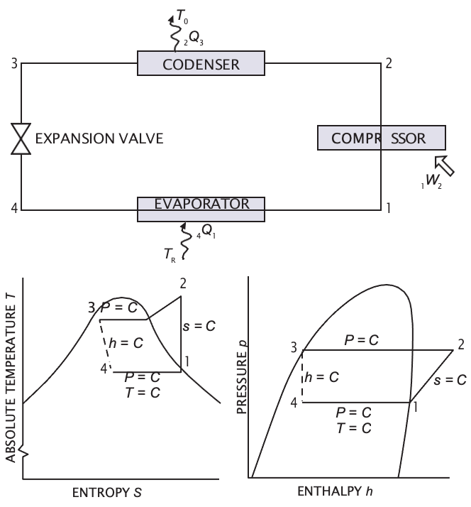
Figure 3.9.The Refrigeration Cycle and Enthalpy Chart
Chillers
The selection of a chiller (from many types) is affected by factors such as energy sources, prime movers, physical size, load requirements, anticipated load profile during the year, and refrigerant selections.
Types. The most common chiller types for central plants are rotary, centrifugal, and absorption, in many combinations (especially in plants constructed in expansion phases). (1) Many rotary screw type chillers, include scroll, single blade (fixed vane), rotating vane, and single screw or multiple screw. Two screw types are explained: single screw (rotary, long bearing life, inherently balanced loads, some with built-in centrifugal economizer) and twin screw (helical, most used multiple screw compressor, formally the double helical rotary screw compressor). Single blade and rotating vane compressors are for smaller applications; scroll compressors are replacing reciprocating compressors for smaller chillers; and screws are common in packaged water chillers. Recent screw chillers with variable-speed drive (VSD) controls have high part-load performance and reduce noise and wear in off-design conditions. (2) Centrifugal chillers are the most popular type in central cooling (simple to operate, low vibration, reliable, compact, relatively quiet, long life and low maintenance). They can be single stage (one impeller) or multistage (two or more impellers), incorporate economizers, and be open or hermetic. Given specific variables, some manufacturers use gear drives to increase small impeller speed while others use direct drives with larger impellers, multiple stages, or both. Direct drive units have fewer moving parts and fewer bearings and are generally simpler. Centrifugal compressor capacity is controlled by three methods: inlet guide (prerotation) vanes, inlet guide vanes plus variable speed impeller (with VSDs and aggressive water temperature resets, the most energy-efficient part-load performance of any refrigerant compressor, with lower noise and reduced wear in off-design conditions), and hot gas bypass (no part-load energy savings; last resort when very low turndown is required and on-and-off cycling cannot be used). When the compressor produces high lift at low volumetric flow, centrifugal compressors can surge, creating noise, vibration, and heat; prolonged surge operation can lead to failure. Surge is relatively easy to detect in the incipient surge phase, when the machine gurgles and churns (unharmful, but with electrical vibrations). (3) Absorption chillers, in many central plant operations, usually use low-pressure steam or hot water (indirect firing) or natural gas (directly fired). Absorption chillers have higher O&M costs (compared to compressor types) and are often uneconomical unless electricity is expensive, fuel costs are low, or electrical and thermal load balancing is needed in cogeneration facilities. The absorption process appears complex but is the same basic refrigeration process. The most common process uses lithium-bromide and water. A double-effect absorption process is similar, but a generator, condenser, and heat exchanger are added, making it much more energy efficient. Variable-speed refrigerant and solution pumps enhance absorption machine controllability.
Refrigerants. Properly working refrigerants have low toxicity, low flammability, and long atmospheric life. Refrigerants are under scientific, environmental, and regulatory scrutiny because of environmental impacts; some, particularly chlorofluorocarbons (CFCs), have high ozone depletion potential. CFCs are being phased out (per the 1987 Montreal Protocol). Halogenated chlorofluorocarbons (HCFCs), the most common replacement, will be phased out in the 21st century but should be available during the life of machines currently being manufactured. Refrigerants are greenhouse gases, with direct effects and also indirect effects due to system energy use, so managers must focus on overall system energy efficiency. A comparison of theoretical and practical refrigerant efficiencies shows only slight differences.
Prime Movers. Several prime movers drive chillers (e.g., most commonly electric motors and steam turbines; reciprocating engines and gas turbines with varying success). Commercial cooling ranks as the highest summer demand on the grid and second highest annualized energy use. Cooling growth is expected to increase greatly, so utilities provide incentives for thermal energy storage systems and district cooling alternatives. (1) Steam turbines work for larger chillers, with a smoothly rotating power source available in all horsepower ranges, often matching compressor design speed without a speed-increasing gear. They sometimes are selected to exploit existing boilers in a central heating plant, saving on capital cost, improving the year-round steam-generating load factor, and possibly reducing off-season fuel rates. (2) Electric motors are the most common centrifugal chiller drives, running at exact speeds if synchronous (and slightly less than synchronous speeds if induction type), but centrifugal compressors operate most efficiently at speeds much higher than motor speeds, so motors need a speed-increasing gear (sometimes eliminated by using a two-stage compressor, custom designed to meet application requirements). Large horsepower sizes operate at almost any voltage, but economics is the key voltage selection factor. Existing electrical service must be assessed for a new large-capacity chiller; a new feeder or a change in transformers might be needed. The central chiller often is the largest electrical load on campus.
Thermal Energy Storage
Renewable energy and the smart grid will have an impact on electricity generation, delivery, use, and purchase. Renewable energy to generate electricity requires a storage component to increase usable output. Some storage technologies (e.g., pumped hydro, long duration flywheels, compressed air storage, sodium sulfur battery storage) can be applied on a large utility grid scale. For customers, lithium ion and lead acid batteries and thermal energy storage (TES) store energy on a building-level scale. Two major TES types, chilled water storage and ice storage, have a large installed base and proven reliability and performance. Simple TES systems have a mechanical cooling device, storage tank, cooling load, and some cooling controls. Generally used at larger facilities with economies of scale, water tanks (e.g., at facilities with chillers, data centers) can be above or below ground and custom designed. The economics of commercial modular ice storage systems enable TES use in more applications. TES systems are affordable (new construction payback in less than 5 years, 7 years or less for retrofits) and last 25 years or more. Application, design, and control best practices now provide reliable and affordable energy storage.
Pumps
In the chilled water plant, centrifugal pumps are the prime movers. Variable-speed motors are considered for the chilled water system, with pump outputs to match required system flows without over-pressurizing the system. Like chilled water pumps, condensing water pumps can be end-suction, horizontal double-suction, or vertical turbine pumps. Pumps use either mechanical or packing gland-type seals. Mechanical seals are adequate if water is clean and water treatment is compatible with the seal material. Replacing a mechanical seal is more difficult and time-consuming than repacking a gland-type seal.
Pump Performance Curves. For a given impeller size and rotational speed, a head-capacity curve shows pump performance. Total dynamic head is the difference between suction and discharge pressure. As the pump delivers more water, pump mechanical efficiency increases until it reaches a Best EPfficiency point (BEP). The pump performance curve can show required power (horsepower) and displays data on Net Positive Suction Head Required (NPSHR). Curves are rated as steep or flat (based on difference between shut-off head pressure and BEP pressure).
Parallel and Series Pumping. When two or more pumps operate in parallel, a combined parallel pump curve holds head constant and adds flow; similarly, a series pump curve holds flow constant and adds head. Variable-speed booster pumps are used if required. For a given impeller size, a family of curves shows variable- speed pump performance, with BEP following a system-like parabolic curve and NPSHR lines following fairly closely with end-of-curve lines for various speeds. Power lines decrease rapidly as speed decreases.
Piping Systems. Major piping system design considerations are system pressure and temperature, pipe velocities (directly related to system pressure loss, inversely proportional to pipe size), pipe material and compatibility with contents, expansion and contraction, supports, and insulation (and balance between initial and operating costs). Thermal expansion and contraction are not large in chilled water systems but cannot be ignored.
(1) The most common central chiller piping is standard- weight black steel pipe with welded fittings (or grooved pipe with bolted couplings). (2) Primary distribution systems are designed after considering pipe size and location (from a thermal utility master plan), future loads, and pumping costs. (3) Material selection depends on initial cost, corrosion requirements, operating pressures, joining methods, and expected
Terminal Components. Maximized cooling coil performance is crucial to system operation. Chilled water temperature differential is determined by terminal device performance. Control valves are needed for all cooling coils and should be selected and located to match the cooling coils they control. Two-way control valves (rather than three-way valves) should be used in large campus district cooling systems.
Heat Rejection
A cooling tower exposes as much water surface area to air as possible to promote water evaporation; about 1 percent of total flow evaporates for each 12.5°F temperature change. Relevant terms include range (temperature difference between water entering and leaving the cooling tower) and approach (temperature difference between water leaving the cooling tower and ambient wet-bulb temperature). Cooling tower performance is a function of ambient wet-bulb temperature, entering water temperature, airflow, and water flow.
Types of Cooling Towers. Cooling towers in a variety of shapes and configurations include direct (open) towers and indirect (closed-circuit fluid cooler) towers. Airflow is driven by a fan (mechanical draft) or induced by high- pressure water spray. Water surface area is increased by using fill (splash-type or film-type, the most common). HVAC systems typically use packaged cooling towers; field-erected towers apply to very large chiller plants and utility projects or to custom towers to improve aesthetics. This section discusses the most common types of HVAC chilled water plant cooling towers: (1) spray towers, which are quiet with low initial costs but seldom used (e.g., easily clogged nozzles, susceptibility to adverse wind effects); (2) forced-draft cooling towers, which are crossflow or counterflow, with axial fans or centrifugal fans (commonly used for ability to overcome high static pressure, low profile, and quiet operation but not as energy efficient as axial fans and more subject to recirculation); (3) induced-draft cooling towers, which are crossflow or counterflow, use axial fans, and are by far the most widely used and energy- efficient cooling tower (usually field erected), not as susceptible to recirculation, subject to noise at low frequencies, and driven by a belt or direct shaft; and (4) closed-circuit fluid coolers, which use closed piping (e.g., for high-pressure fluid, mixed fluids, remotely located primary pump) and treated fluid, are physically much larger, and are more expensive than conventional open towers.
Application Issues. (1) Siting and recirculation is a greater risk with forced-draft towers and with towers confined in pits or by screen walls. If saturated air leaving the cooling tower is drawn back into the tower intake (e.g., because of wind forces or adjacent towers), the resulting recirculation degrades performance. The Cooling Tower Institute recommends recirculation effects as a factor in cooling tower selection. (2) Capacity control is needed when cooling towers are selected for maximum peak capacity at design weather conditions but operate most of the time below that level. Temperature control for water leaving a cooling tower uses on-and-off cycling (least favorable), two- speed and pony motors, variable-speed drives (VSDs, with lower initial cost, tighter temperature control, lower operating costs, reduced noise, control data), and modulating dampers (just for centrifugal fans). (3) Chemical treatment and cleaning are needed for cooling towers, which require regular cleaning and inspections (e.g., to avoid disease). There are very good air scrubbers but corrosion and calcium carbonate precipitates on condenser tubes occur; contracting with a chemical treatment specialist is best, with strategies such as blowdown, scale prevention, corrosion control, biological growth control, and foam and scum. New treatment and cleaning technologies (e.g., ozone in cooling water, ultraviolet lights, electromagnetism) are available. (4) Cooling tower performance varies based on fan selection, flow rate, range, fill volume, and entering wet-bulb temperature. Typical performance curves show the relationship between these variables in various operating conditions. Compared to total chiller plant cost, cooling towers are low cost; increases in incremental tower size and energy efficiency are very low cost. Matching larger fill volumes with lower fan capacities is a strong investment. For a given cooling tower design, the manufacturer normally attributes a maximum and minimum flow condition to the tower.
Propeller fan cooling towers use half the energy of centrifugal fan towers for the same duty and have a lower initial cost. If acoustics are important, low-noise draw-through towers with propeller fans are an option (quiet, less costly, better energy performance). (5) Cooling tower accessories include filters, fan breaks or stops, vibration switches, ladders and access platforms, vortex-breaking inlet screens, and sump heaters (see Figure 3.10).
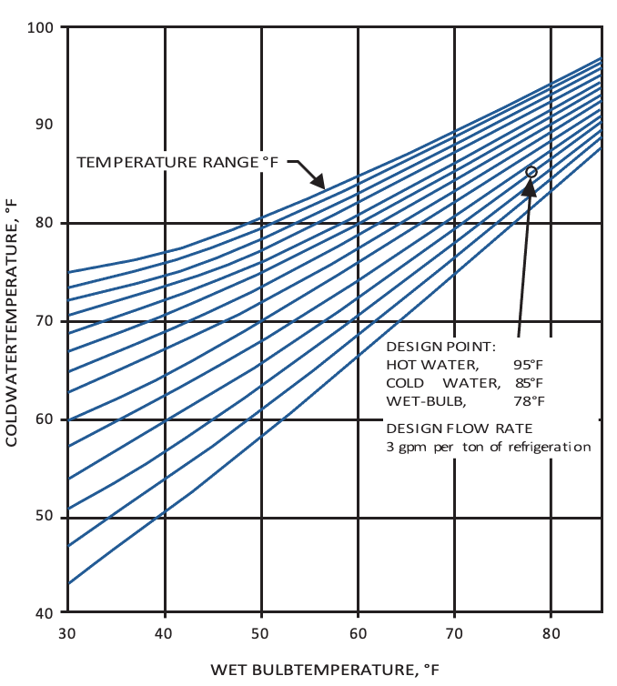
Figure 3.10. Typical Performance Curves
Auxiliary Equipment
Chemical Feed Systems. Two chiller plant water systems require conditioning and treatment, condenser water systems and chilled water systems.
Sidestream Filters and Separators. A filtering system removes solids (e.g., dirt, rust, debris) from the chilled water. Individual strainers and filters are required on sensitive equipment. Sidestream filters installed in the chiller plant can continually filter a small portion of total flow.
Chilled Water Makeup. Chilled water makeup (from a storage tank or domestic water system) replaces losses from leaks and maintenance activity and regulates overall system pressure. The number of potential makeup locations should be minimized. Makeup is measured by a conventional water meter.
Expansion Tank. Expansion tanks are required on chilled water systems to accommodate the expansion and contraction associated with any thermal liquid system and to provide a point of constant pressure.
Automatic Air Release Vents. Air is trapped in the chilled water system whenever equipment or piping is restored to service after chilled water is drained from the system, so automatic air release valves are added to high points in the system (e.g., chillers, tanks, piping, terminal equipment) where air can be trapped.
Controls and Instrumentation. Operating and safety controls are part of the chiller package, but other instrumentation (e.g., pressure gauges, thermometers, flow measuring devices) are specified if required.
Metering. Chilled water systems are metered to measure system and individual component performance as well as energy inputs and outputs. Flow-measuring devices are installed in chilled water, condenser water, steam, and cooling tower makeup water lines. Chilled water meters have many flow-sensing elements, several temperature-sensing devices, and an electronic processor to receive input and calculate and the total energy. Programmable electronic devices can communicate with even more sophisticated centrally located computer systems. Chilled water meter accuracy is a function of the turndown (range of the sensing), precision of flow-measuring element, and accuracy of temperature-sensing device. For a meter to function within its accuracy range, routine calibrations must be made and recorded.
Insulation. Thermal insulation is required on chiller evaporators, refrigerant suction lines, compressors, expansion tanks, chilled water supply and return lines, and any equipment connected to the chilled water system that is subject to sweating. Chillers, heat exchangers, and tanks should be insulated (e.g., with fiberglass, cellular glass, closed-cell foam rubber sheets). Acoustic insulation can be necessary to reduce noise level (e.g., on chiller condensers, compressor discharge piping). Removable heads on chillers and heat exchangers should be insulated. Low-temperature insulated piping in the chiller plant, buildings, and vaults should be insulated at each hanger, support, and anchor. Soil temperatures at burial depths determine energy loss with direct-buried uninsulated pipe and with various insulation materials, so an energy evaluation is needed at each central chilled water site.
System Design Considerations
Central chilled water system criteria are a set of requirements for design and operation of equipment and thermal systems (e.g., central chiller plant, distribution and building systems). Operating problems in many central cooling systems are traced to incompatibility among chilling equipment, piping systems, and terminal loads. Before selecting piping and pumping configurations, proposed or existing systems must be studied, with a full hydraulic analysis (one of the most important steps before capital investment), component compatibility and energy analyses, and installation operating costs. Common piping and pumping systems in chilled water systems are primary, secondary, and tertiary loop systems, with many layout options. Chillers can be connected to individually dedicated cooling towers or a common header, but physical layout must be fully analyzed for equipment compatibility.
Pumping and Piping Systems. Pumping costs must be minimized to keep overall chilled water system efficiency as high as possible. Flow rates to individual components and bypasses around equipment must be minimized. To prevent overpumping, pumps with variable-frequency drive should be installed.
Chiller Plant. Good design provides for future expansion and anticipates the flexibility needed to take advantage of new ideas, equipment, and technology. Primary central chiller plant design concerns are the process, equipment and support system layout, maintenance access, and future expansions (not the site and building). System reliability depends on component quality, durability, and preventive maintenance.
Redundant equipment can be used for seasonal load variation and reliability, critical environments, and certain electricity demand rates. System criteria to select equipment and develop operating procedures must be set when the central chilling plant design is started.
System criteria requirements are relevant when the plant is expanded or a new building is added. Critical design elements are system reliability, performance, and serviceability. Initial decisions have significant implications for plant size. Pumping for water circuits in a central chilled water plant fall into categories: (1) unitary, a single pump dedicated to a specific chiller, used in primary and variable primary flow pumping systems and in condenser water pumping systems; (2) primary/secondary, with chiller and in-plant piping hydraulic head needs supplied by pumps dedicated to specific chillers (and distribution system needs supplied by a separate decoupled pump circuit); and (3) headered, with pumps discharging into a common header serving a bank of chillers, used in primary flow and variable primary flow pumping systems and condenser water pumping systems.
Building Interconnection. Building connection analyses are important for the full chilled water system. Tertiary loops are avoided at building connections. Low return temperature primarily results from poorly selected coils or coil control valves. During coil acquisition and installation, technicians must make sure that coil performance maximizes chilled water temperature differential and still meets building cooling needs.
Hydraulic interfaces between central systems and building systems vary in control strategies but generally use a straight primary interface or a variable-speed booster pump building interface.
System Performance
Diversity Factor. The diversity factor is the relationship between the sum of peak loads for individual buildings and the actual aggregate central system peak load.
Predicting diversity is difficult with new systems, but existing buildings are assessed with metering. Central plants can be designed for a capacity of something less than the sum of the individual buildings.
Load Factor. The load factor is the ratio of total cooling energy produced over a year to total potential generated by installed chilling equipment. It depends heavily on climate and load types. Even with a 25 percent load factor, chilled water systems can deliver much more chilled water than actually generated. Adding year-round process loads increases the load factor without substantially affecting peak demand.
Load Duration Curves. These curves show central plant installed capacity, load demands, time per year for system load operated at each level, and an optional thermal storage element. Load duration curves are helpful in sizing equipment. Horizontal lines show available capacity as each chiller operates; multiple units allow chiller generation capacity to better match overall system needs by sequencing chillers to match load profile, but the cost of many small machines (versus fewer larger machines) is much higher. The load duration curve can exceed the plant installed capacity curve; solutions are shedding noncritical loads a few hours per year or (in some systems) having the full system uniformly shed load.
Building Performance. Peak chilled water demand for specific building types is calculated by applying industry standards for gross square footage per ton; specific building demand is calculated by multiplying the building square footage by this factor. Individual buildings have larger performance factors if they are served by localized equipment because central cooling systems experience load diversity.
Total, Firm, and Reserve Capacity. Central chilling plants often have multiple water chilling units, cooling towers, pumps, boilers, and other equipment; each is out of service at some time for cleaning, maintenance, or repairs. Total capacity is the sum of capacities for all installed units. Firm capacity is the sum of all installed units minus the capacity of the largest unit. Reserve capacity is any plant tonnage above the maximum system demand, up to firm capacity.
Operation and Maintenance
Full-load and part-load performance data determine which chiller (or chillers) cools most efficiently.
Maintenance. Each chiller has a manufacturer- recommended refrigerant charge based on maximum summer cooling. Reducing the charge during low load operations saves significant energy. Chiller condenser and evaporator heat exchanger cleanliness must be monitored to determine when equipment must be cleaned. Automatic online tube-cleaning systems (brush or sponge rubber ball) for chiller condensers are proven energy conservation methods.
Energy Audit. These audits are vitally important for larger equipment (e.g., chillers) that use the most energy. Energy input divided by output (kilowatts per ton or pounds of steam per ton) is a convenient performance yardstick. A heat balance is periodically needed on all major equipment. Many plants have computer-based data logging systems that monitor performance continuously, sound alarms if limits are exceeded, capture all data, and provide operating profiles (by hour, day, week month, year).
Energy Conservation and Optimization. (1) Chiller compressor power use increases as compressor head (pumping energy) increases. (2) Free cooling can be used when central cooling systems operate all year; savings are realized by using cooling tower condenser water for cooling in cool weather; a heat exchanger and possibly cooling tower freeze protection are needed.
Small localized cooling systems can extend the free cooling season, enabling large chilling equipment to be turned off for extended periods (in northern climates, as long as 6 months a year). (3) Thermal storage systems tend to be large (especially if storing chilled water rather than ice). Some utilities participate in thermal storage projects and offer lower rates for night or off-peak use. (4) Load shedding (e.g., turning off equipment, using an energy management control system, increasing chilled water supply temperature to terminal units, chiller loading to maximum capacity) can be needed when system demand for chilled water exceeds available or economical capacity. All users should understand the load shedding and provide feedback.
Water Treatment. Water treatment reduces fouling of chiller heat exchangers and system corrosion. Consulting professionals can formulate, oversee, and monitor water treatment programs and efficiencies via laboratory analysis, and vendors can provide complete turnkey systems.
Cooling Tower. The open circulating condensing water system is subject to scale formation, corrosion, slime, and algae; it also offers optimum conditions for microbial growth. Scale control by blowdown or bleed-off works in some cases, but pH control also can be needed. Microbiological treatment programs use oxidizing and nonoxidizing biocides.
Chilled Water. Each time a building is added to the system or distribution piping is modified, the chilled water system is contaminated to some degree, depending on new pipe condition and advance flushing and cleaning. Chilled water system chemical treatments often include adding a corrosion inhibitor via feeder.
Water Makeup Monitoring. Knowing the quantity of chilled water makeup required for the system enables quantification of any system leaks or dumping.
Communication. Information (e.g., on operations, rates, growth, outages) must flow freely among the three commonly defined territories of the chilled water system (building, distribution, generation).
Training. Institutions must train entry-level employees and then maintain and improve O&M staff skills (e.g., equipment start-up and shutdown, operating parameters, energy optimization, routine maintenance). Factory training is considered when major equipment overhauls or additions are implemented.
Staffing. Central chilled water plant staffing is driven by system size and complexity and integrated with other central utility services operations. Staffing and organization vary but often consolidate production efficiency and utilization efficiency functions, which drive total system performance. The scope of in-house staffing for maintenance requires careful review, but specialty services (e.g., oil sample analysis, eddy current testing) are provided most economically as contract services.
Retrofit. System retrofits are considered if they substantially improve central chilled water system operating efficiencies and reduce operating costs. If chilled water systems serve relatively constant loads during the year (e.g., computer systems, clean rooms), installation of small stand-alone chiller units can enable central system shutdown during winter months (or extension of the free cooling season).
Leave a Reply
You must be logged in to post a comment.