 Create an Account
 Login/myAPPA
 Bookstore
 Search
  Translate
Networking technologies (initially part of administrative overhead) serve as the telecommunications backbone of most universities and play a critical operations role.
Network technologies have evolved because of data distribution (e.g., virtual disks and data archives; subject to network outages and poor network performance such as congestion and latency); application distribution (e.g., email and business systems, usually with a client-server architecture but more recently web based); convergence of data, voice, and video services (e.g., VoIP to replace legacy telephony systems; video technology use); integration of stovepipe networks (e.g., building automation, access control, intrusion, fire alarms); and reliance on Internet connectivity (e.g., reliable, robust internal and external communications).
VoIP as a Driver of Converged Networks Universities usually incurred the cost of installing and operating dual network infrastructures, one for plain old telephone service (POTS) and one for data networking services (with cabling installed as an afterthought). VoIP now is the main factor driving converged networks; the major benefit is a single physical cable plant designed to carry both voice and data traffic. VoIP has features such as integration with campus directory services, advanced ACD, and a programmatic interface for application integration.
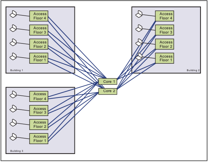
Figure 3.15. An Example of a “Collapsed Backbone” Network Architecture
Network Architectural Model
As additional requirements develop, networks were expanded with available or inexpensive technologies, over time creating suboptimal routing paths and congestion and impeding sustainable network growth. Designing and adhering to a network architectural model avoids these problems.
“Classic” Network Architectural Model. This model has three layers. (1) The access layer is the point of connection for end-user systems, usually located in a telecommunications room (TR), often at least one TR per floor. UTP cables run horizontally from the TR to end- user workstations; uplink cables from the access layer to the distribution layer run vertically over UTP or fiber optic cables (based on distances and speeds). (2) The distribution layer aggregates access layer connections and links them to the core layer, usually with one distribution layer per building and fiber optic uplink cables. (3) The core layer is the network backbone, interconnecting distribution layers and using fiber optic cables to connect core layer devices, usually in a fully meshed topology to provide fault tolerance (see Figures 3.15 and 3.16).
Resiliency Improvements. Network fault tolerance is improved by pairing adjacent buildings and adding resilient connections from the access layer of one building to the distribution layer of the other building and vice versa. Resiliency is not normally designed into the access layer because most end-user workstations have only a single network interface card.
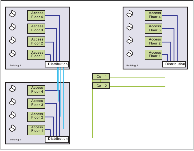
Figure 3.16. An Example of a “Classic” Network Architecture
Collapsed Backbone” Approach. This design has only access and core layers (e.g., for a small number of buildings or users), reducing cost; the access layers in each building are dual-homed to two core layers for resiliency. This design can be easily modified for a classic three-tiered design in the future.
Structured Cabling Systems
Introduced in the 1980s to standardize building wiring installation, structured cable systems keep cables tidy, prevent accidental damage, and create a design-once, build-many model that is easily replicated.
Access Layer to Workstation. The 100- and 1,000- Mbps (and evolving 10-Gbps) Ethernet standards specify the maximum length of a cable run from the switch port to the end-user computer (inclusive of all patch cables) to avoid excessive signal attenuation, degradation, and ultimately data transmission errors.
UTP Wiring Selection. The common standard for end- user workstations is Ethernet delivered over UTP wiring. Selection considers existing speeds and potential growth and new technologies. EIA/TIA Category 5 wiring supports speeds up to 100 Mbps, with Category 5e and Category 6 supporting up to 1,000 Mbps. Wiring is usually installed during building construction, and rewiring is possible only with a major renovation. New installations should consider Category 5e at a minimum.
Adherence to Local Building and Fire Codes. The correct cable jacket composition type must be used according to local fire regulations. A higher FT rating indicates less susceptibility to being a combustible material and possibly a lower level of toxic material emission when burned.
Termination at the Workstation End. The cable run is normally terminated at the end-user workstation with an RJ-45 jack (and a patch cable). Jack numbering and labeling nomenclature is used to mark each cable run at the user connection and in the TR. Commercial database products support record keeping.
Termination in the Telecom Room. Cable runs normally terminate in the TR on a patch panel (based on one of many patch panel standards), with patch cords connecting individual cable runs to switch ports.
Protection of the Cable Run. Cable runs from the TR to end-user workstations are protected as possible (e.g., enclosed cable trays or conduits; no nearby electromagnetic or radio frequency interference sources; no nearby AC power cables, transformers, electric motors, photocopiers). Wiring testers (e.g., Fluke or Tektronix) can determine whether external interference is causing data errors.
Cable Plant Certification. Some organizations adhere to an industry or vendor standard such as NORDX/IBDN or AT&T Systemax and build their cable plants to achieve these vendor certifications.
Location of the Telecom Rooms. Factors in locating TRs include meeting 100-meter horizontal run limits, basing TR footprints on number of end users, running vertical conduits via (stacked) TRs, using lockable restricted access and intrusion alarms, powering installed equipment (with growth overcapacity), providing ventilation and cooling, using UPS systems, and dedicating TRs to switches or routers.
Location of Telecom Rooms Containing Core Layer Equipment. Power failure, construction damage, and natural disaster outages tend to be localized, so core layer equipment TRs are in different buildings.
Uplink Cables Between Access and Distribution Layers. Cables between floor TRs and the distribution layer can use UTP or fiber optic cables. Most organizations link access layers to the distribution layer via fiber optic cables, either multimode (usually up to 2,000 meters in length) or single mode (up to 10,000 meters in length); specific maximum distances depend on the manufacturer.
Location of Telecom Rooms for Distribution and Core Layers. The same general considerations apply when selecting TRs for the distribution and core layers as for the access layer. The building distribution layer and floor access layer commonly are in the same room, where a core layer also could reside.
Uplink Cables between Distribution and Core Layers. Because distribution and core layers are typically in different buildings, fiber optic cables are common (usually single mode to maximize future flexibility in length and speed). On large campuses, the physical cable layout often has two or more interconnect junction points and then connects each building to the common locations. Two distribution uplink cables from each building should take a diverse physical path to protect against cable cuts.
Network Management Considerations
Network management is a large topic, but most organizations need to deliver reliable service and thus at a minimum must have knowledge about network component status, traffic levels at key connection points, and real-time alerts for the staff if a device fails or traffic exceeds performance thresholds. Most network devices (e.g., switches and routers) support SNMP. Many software applications monitor availability, from open source (free) tools to fairly low-cost commercial products (e.g., What’s Up Gold; Intermapper) to high-end packages (e.g., Openview). Many traffic and performance monitoring tools are available; most universities use open source tools such as MRTG or CACTI.
More Information
These technologies continue to evolve at a fairly rapid pace, so facilities managers should consult industry standards (e.g., TIA/EIA copper and fiber wiring standards; IEEE Ethernet technologies standards); keep abreast of emerging trends and associated impacts on the campus physical plant infrastructure; and coordinate with information technology groups that provide computing and communications services and with other groups responsible for building automation or access control.
Leave a Reply
You must be logged in to post a comment.